10+ uml entity diagram
Learn about UML BPMN ArchiMate Flowchart Mind Map ERD DFD SWOT PEST Value Chain and more. Where use cases are used to represent the set of activities services that the system needs to perform and actors are the entity that works under defined roles within the system.
How To Show A Weak Entity Relationship On A Class Diagram Quora
Figure notation for dependency relationship Class diagrams component diagrams deployment and object diagrams use dependency relationships.
. Student Score - Binary Relationship. An entity-relationship diagram consists of three basic elements such as entity relationship and attribute. The object orientation of a system is indicated by a class diagram.
Can anyone please. An actor is used in a use case diagram to describe the internal or external entities. Entity Boundary Control Entity X X Boundary X Control X X X Share.
In simple words it describes how many elements are taking part in an interaction. ER diagrams enable software engineers and system analysts to model and design their databases and information systems. In my previous article on sequence diagrams I shifted focus away from the UML 14 spec to OMGs Adopted 20 Draft Specification of UML UML 2In this article I will discuss Structure Diagrams which is a new diagram category that.
Student Score - Ternary Relationship. The concepts behind it are about organizing the way a device computer program or other often technical process works such that an entity or each of its. Follow edited Jan 19 2017 at 1858.
Association describes how the elements in a UML diagram are associated. There are three basic elements in an ER Diagram. Diagrams have been used since prehistoric times on walls of caves but became more prevalent during the Enlightenment.
Actor An external entity that interact with the system. Sometimes the technique uses a three-dimensional visualization which is then projected onto a two-dimensional surface. An Entity Relationship ER Diagram is a type of flowchart that illustrates how entities such as people objects or concepts relate to each other within a system.
A sequence diagram is composed of elements and icons which you need to be familiar with in order to create one. Other notations used to make ERD diagram examples include cardinality and ordinality to define relationships in. In November we released UML diagrams for the Visio web app.
It is the most popular UML diagram in the coder community. ER Diagram Example. Flowchart Maker and Online Diagram Software.
The purpose of the class diagram can be summarized as. For example in a customer service application the Customer entity would manage all data related to a customer. When it comes to system construction a class diagram is the most widely used diagram.
Analysis and design of the static view of an application. A dependency is used to depict the relationship between dependent and independent entities in. Learn from diagram examples and start creating your diagrams online.
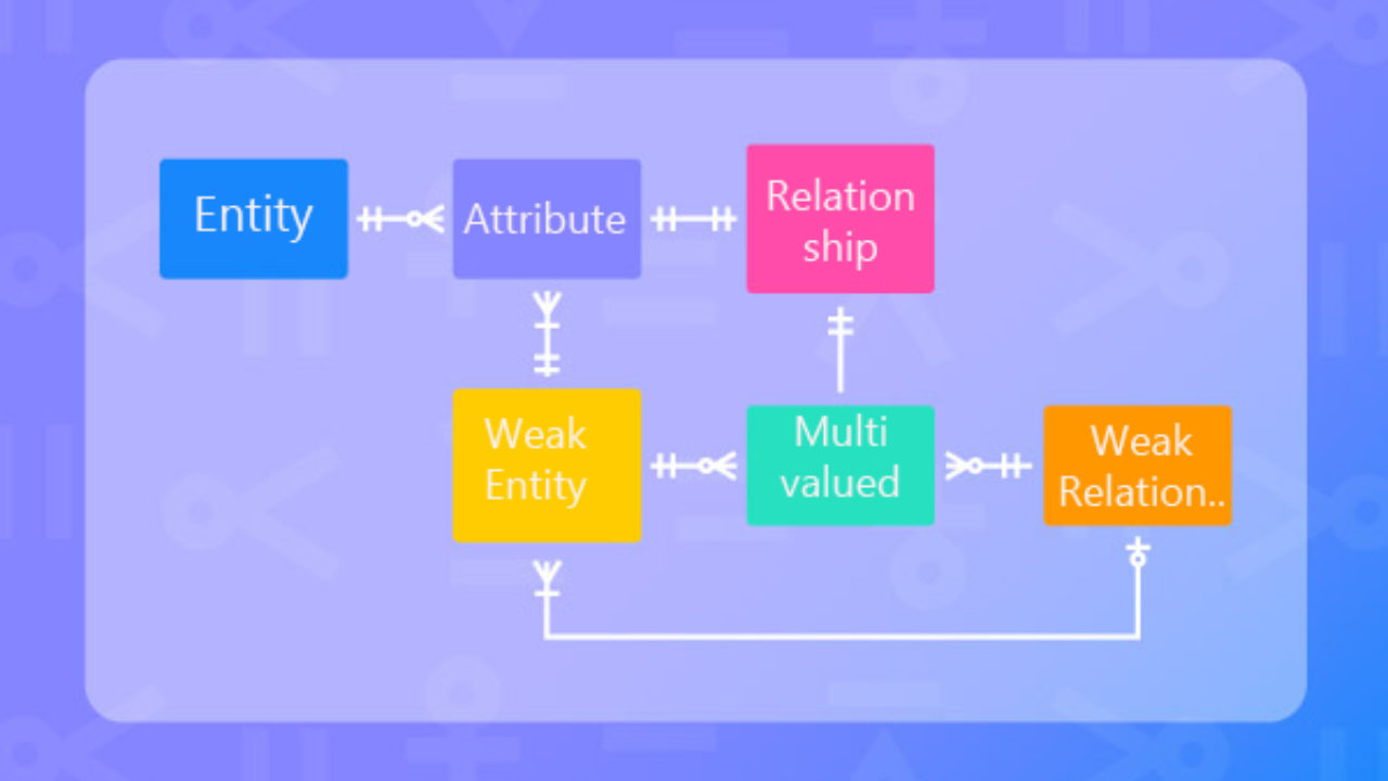
Along with these are more components based on their main elements like weak entity multi-valued attribute and many more. UML diagrams like activity diagram sequence diagram can only give the sequence flow of the application however class diagram is a bit different. Dependency Relationships We use a dependency relationship to show when one element depends on another element.
Answered Jun 10 2013 at 1641. Work virtually anywhere anytime with the Visio web app. An example of how to read a diagram would be nice.
The ER Diagram show the relationship between entities tables and the primary key-foreign key relationships between the tables relationships. Such a diagram would illustrate the object-oriented view of a system. The word graph is sometimes used as a synonym.
An actor can be defined as some internal or external entity that interacts with the system. In the class diagram there are model elements known as Boundary Class Control Class and Entity Class. UML Class Diagrams is a type of static structure diagram that is used for general conceptual modeling of the systematics of the application.
UML use case diagram is one of the types of UML diagram which is used to represent the dynamic diagram by mapping the structure of the systems using actors and use cases. ER Diagrams are most often used to design or debug relational databases in the fields of software engineering business information systems education and research. A lifeline with an entity element represents system data.
UML state machine also known as UML statechart is an extension of the mathematical concept of a finite automaton in computer science applications as expressed in the Unified Modeling Language UML notation. A diagram is a symbolic representation of information using visualization techniques. Im now using NetBeans as my IDE-of-choice and it has a plugin for UML modeling.
Since then many of our users have been asking for the inclusion of Entity Relationship Diagrams ERDs to help them model their databases. There are more elements which are based on the main elements. I want a relationship between er diagram and uml diagram.
There are basic symbols components and types of message arrows that may occur in a UML sequence diagram example. Access templates and shapes for specialized diagrams including cross-functional flowcharts and detailed network Azure AWS ERD and UML diagrams. The easiest and one of the best tutorial for learning about UML Sequence diagram.
Hi I have to do an ER model for a travel game app but we have not been shown how in college. Drawio can import vsdx Gliffy and Lucidchart files. You can use it as a flowchart maker network diagram software to create UML online as an ER diagram tool to design database schema to build BPMN online as a circuit diagram maker and more.
An entity is a thing person or. Entity-relationship modeling or ER Diagram symbols are part of a conceptual approach to design that models objects as abstract data types and the relations between these objects as predicates. This is the next installment in a series of articles about the essential diagrams used within the Unified Modeling Language or UML.

Entity Relationship Diagram Erd Er Diagram Tutorial Relationship Diagram Activity Diagram Tutorial
Information Model Wikiwand
How To Show A Weak Entity Relationship On A Class Diagram Quora

Entity Relationship Diagram Erd Example Physical Erd Of An Online Photo Album This Er Model Example Database Design Relationship Diagram Diagram Design
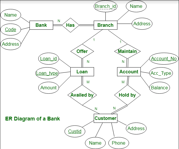
Er Diagram Of Bank Management System Geeksforgeeks
How Do We Read Cardinality In A Uml Diagram Or In E A Diagram Quora

Dbms Case Study Dbms Database Design Management Information Systems
How Do You Draw A Visual Paradigm Entity Relationship Diagram

Er Diagram Tool Chen Erd Relationship Diagram Diagram Design Diagram

Entity Relationship Diagram Entityrelationshipdiagram Relationship Diagram Diagram Erd

Entity Relationship Diagram Erd Example Logical Erd Of An Online Photo Album This Er Model Example Is Brought To Database Design Relationship Diagram Erd
How To Show A Weak Entity Relationship On A Class Diagram Quora

Admin And User Chen Er Diagram Relationship Diagram Data Modeling Diagram

10 Erd I E Entity Relationship Diagrams Interview Q As Java Interview Questions Big Data Interview Questions
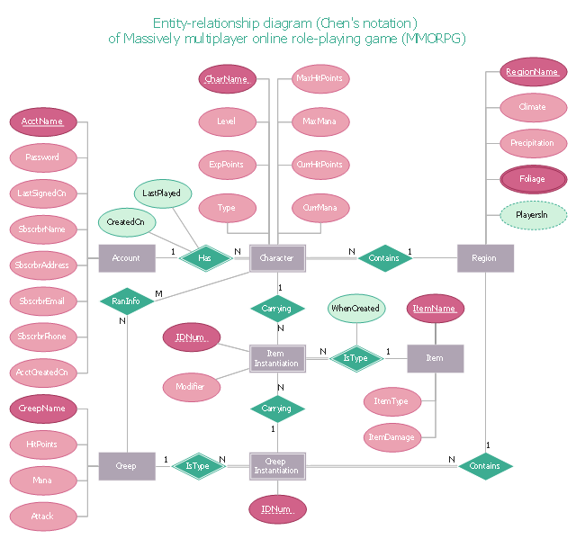
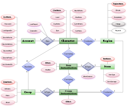
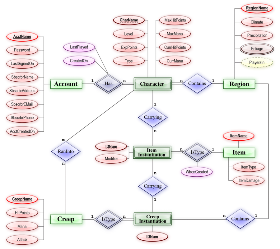
Chen S Erd Of Mmorpg Android Gui Examples Of Flowcharts Org Charts And More Erd For Online Multi Player Game
Entity Relationship Model Wikiwand

Dbms Case Study Dbms Erd Management Information Systems